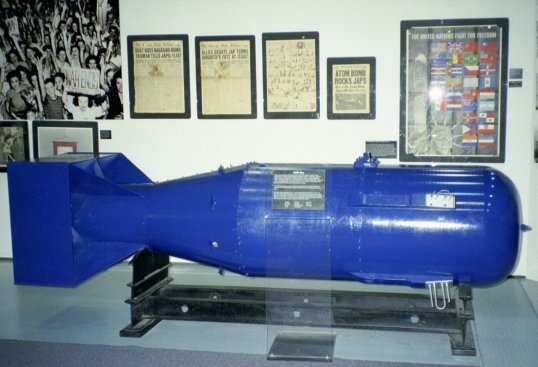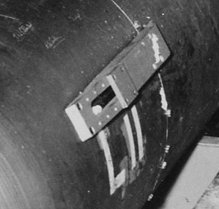

Notice the antenna towards the front of the bomb. The antenna is silvery colored, probably aluminum. It has one loop with two straight rods on each side of the loop. It sets on a rectangle which is also silvery colored. You should be able to see two sets on each model. Presumably, there's another pair behind the model which are hidden from view.
Look at the lengths and spacing of the elements. This is important in an antenna because it determines the frequency and pattern. This antenna that is shown on these models had a patent: 2452073 Compare the relative length and spacing of the antenna on the models with that of the drawings from the patent, shown below.
https://www.google.com/patents/about?id=VotOAAAAEBAJ
UNITED STATES PATENT OFFICE
2,452,073 FOLDED DIPOLE
George William Schivley, Buchtel, and Paul W. Springer, Dayton, Ohio
Application November 17,1944, Serial No. 563,980 1 Claim. (Cl. 250—33.65)
(Granted under the act of March 3, 1883, as amended April 30, 1928; 370 O. G. 757)
The invention described herein may be manufactured and used by or for the Government for governmental purposes, without the payment to us of any royalty thereon. :
The present invention relates to directional antennae.
An object of the invention is to provide a radio antenna for use on the tail of an aircraft in circuit with a warning device, to warn of the presence of another craft in flight within a predetermined range.
A further object is to provide such an antenna which may be applied to various types and sizes of aircraft with a minimum of adjustment.
A further object is to provide such an antenna which is of light weight, highly directional, of controllable wave pattern and range, simple'to manufacture and install and highly efficient in use.
These and other objects will appear throughout the specification and will be pointed out in the claim.
The use of reflected radio wave pulse transmitting and receiving instruments to signal the presence of distant objects is • particularly indicated for use in warning a pilot in flight, particularly a fighter plane pilot, of the presence of an enemy plane just outside firing range directly behind the tail of his plane.
The difficulties of adapting such radio equipment, however, have centered about the control of the emitted and received radio waves so that only reflected waves from planes within the vulnerable area behind the tail and within firing range be indicated. If such warning equipment were actuated by neighboring flight formations, ground signal, or planes beyond firing range, it would inevitably endanger and confuse the pilot. The use of a unidirectional antenna would aid in the direction of the transmitted waves to the rear of the plane. Available antennae, particularly the Yagi type, when applied to the tail fin of a plane, have the disadvantage of requiring, individual tuning for every plane since the thickness of the fins on different aircraft on which the antenna is to be mounted, is subject to considerable variation. The necessity for weight reduction of this auxiliary equipment also limits the usefulness of such antenna because of its low efficiency when bilaterally shrouded.
The present invention utilizes a quarterwave two-section unidirectional dipole antenna of the folded type, one section of which is attached to each side of the airplane vertical fin. These two antenna sections are electrically joined together by a looped phasing and balancing cable section so that regardless of the spacing between the two sections, any variation in width of fins is automatically taken up by the slack in the loop without in any. way affecting the balancing or tuning of the antenna-transmitter-receiver circuit. By such a laterally adjustable construction, the entire problem of antenna installation to various types and sizes of aircraft becomes so simple that installation may be easily accomplished by inexperienced persons unfamiliar with radio circuit balancing or slotted line technique. Once the size of antenna is established by the manufacturer, in balance with the transmitter and receiver, variation in width of tail fin will not affect the range, direction or pattern of the radiated waves, as is the case with rigid Yagi type antennae, in which covering or uncovering of the projecting antenna by the fin surface would change the length and consequently the characteristics of the antenna.
Fig. 1 is a top plan view of the antenna in location with respect to its parasitic reflector, and director;
Fig. 2 is a side elevation on a reduced scale of the antenna shown in Fig. 1, illustrating the normal relationship of antenna and aircraft tail fin;
Fig. 3 is an enlarged schematic diagram of the antenna shown in Fig. 2, illustrating the circuit connections;
Fig. 4 is a cross-sectional illustration of the horizontal field or wave pattern obtainable with the antenna herein described; and
Pig. 5 is a vertical cross-section of the wave pattern horizontally sectioned in Fig. 4
By way of illustration, the preferred embodiment of the invention, as applied to an aircraft tail fin or wing comprises a folded dipole two section antenna, generally referred to as 10 and composed of two U-shaped rods 11 and 12 threaded at their ends for bolting to a pair of assembly plates 13 and 14. Bolted to these plates 13 and it in the plane of the legs of the U-shaped antenna II and 12 and spaced therefrom a pair of parasitic reflector rods 15 and 16 project outwardly parallel with the U-shaped antenna leg sections 11 and 12 and for a greater distance. Parallel with and also in the plane of said antenna sections 11 and 12, a pair of director rods 17 and 18 extend from said assembly plates for a distance less than that of either the parasitic reflectors or the antenna sections. Looped between and electrically connecting one of the adjacent 11 and 12 is a cable 21. This cable is of the coaxial type so that the core conductor 22 may be used to connect the insulated antenna ends 19 and 20 by connectors 23 and the outer conductor 24 may be electrically connected to the grounded assembly plates 13 and 14 by connectors 25. Cable 21 is made an odd multiple of one-half the wave length used in transmission and reception over the antenna. This length of cable has the effect of dividing the current from conductor 26 equally between antennae 11 and 12 and of making the currents in these two antennae equal and in constant, or like, phase in the sense indicated by the arrows in Figure 3. Another length of this coaxial conductor 28 connects the antenna and assembly plates with a radio transmitter and receiver svstem 30.
When so arrayed and in circuit with a pulse transmitter and receiver through coaxial, cable 26; the resultant quarterwave radiated- field or coverage is substantially that of a, cone of 90 degrees in vertical, 60 degrees horizontal at half power with apex at the tail fin; the center- line of the -cone angle extending parallel with the axis of the aircraft. By suitably spacing and balancing the size of :the array the impedance of the array -can be made to match that of any standard coaxial line. The pattern shape can be governed to some extent by suitably spacing the elements. The. characteristic pattern of, the radiated and. reflected waves will remain constant regardless of the space separation (within practical limits) between the opposite faces of the tail fin (and consequently of the antenna sections) which is spanned by the coaxial cable loop 21.

