In this post I am pointing out anomalies in the US Declassified Nuclear Test Film #16 viewable here on YouTubes' talkingsticktv channel.
http://www.youtube.com/user/talkingsticktv?blend=1&ob=video-mustangbase#p/c/EFFE6316B694B346/52/qWJntPheYLYIt deals with the the effects of blast on the wings of a B-50 bomber flying close to the supposed "DIXIE" Nuclear Test at Frenchman Lake on 6th April 1953.
The film purports to show filmed evidence of wing vibration caused by the blast wave. From my analysis of the wing vibration clips I can only draw the conclusion the vibration clips were "faked".
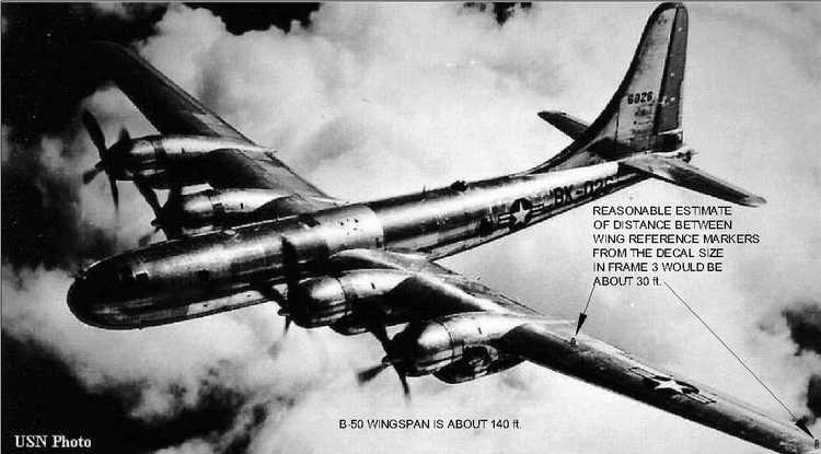
On the above photo of a B-50 bomber I have indicated with reasonable accuracy the positions of the two reference markers on each wing, deduced from the following wing vibration clips, the size of the decal and a dimensioned schematic of the aircraft. The wing marker at midspan appears to be about 30 feet away from the marker on the wingtip.
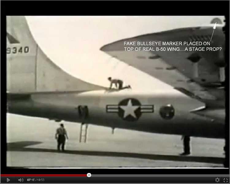
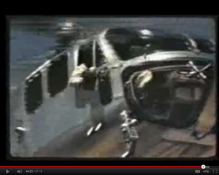
This sequence shows the aircraft being made ready for takeoff before the test
The frame at 07:16 above shows the wing tip marker which appears to be about 12 to 15 inches diameter although it could be even smaller which would make the anomaly even more damning. I still have to do further estimates from the schematic to confirm this.
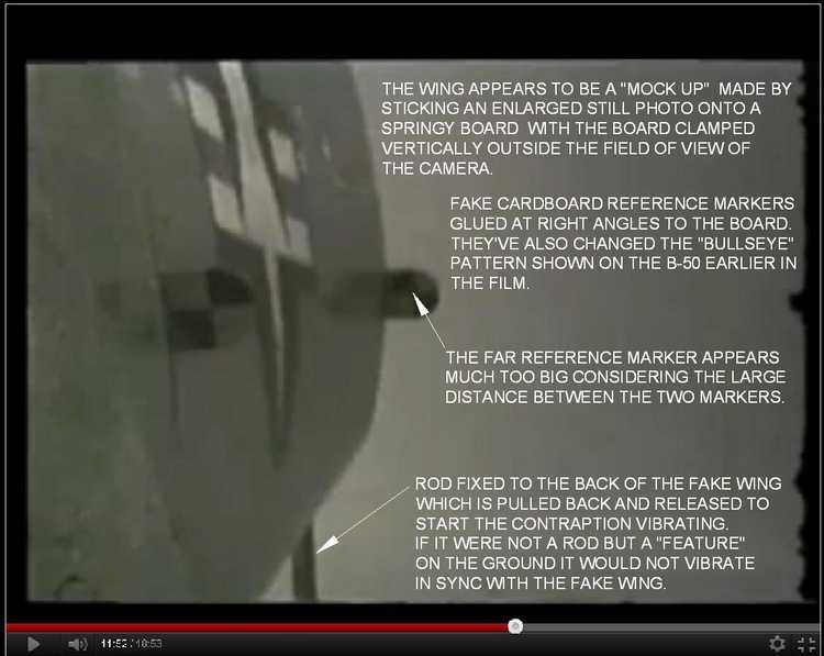
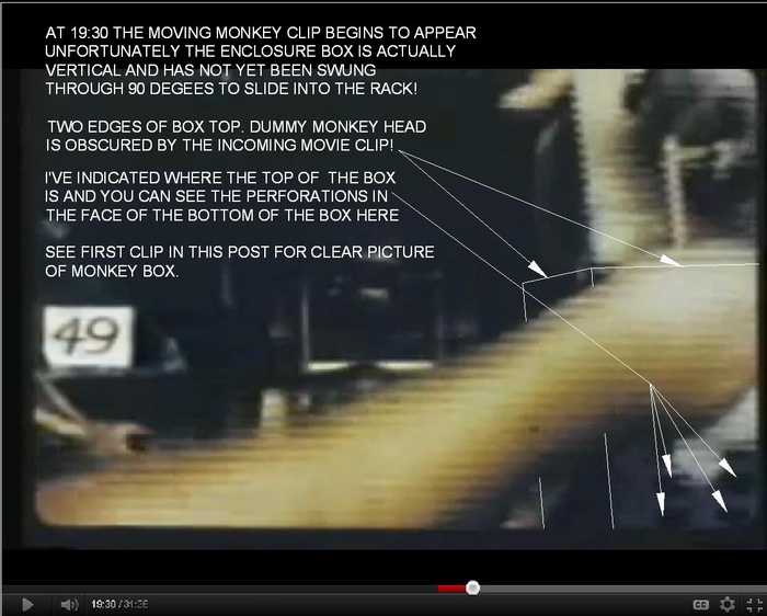
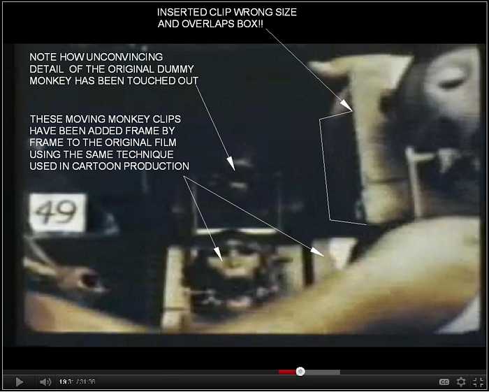
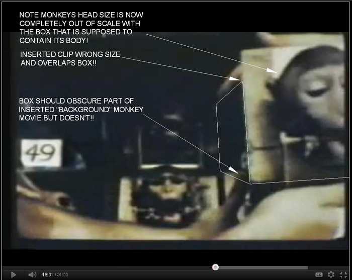
At 11:52 we see a left wing sequence which should have been thrown on the cutting room floor as it betrays how the vibration sequences were faked. See the annotation for an explanation.
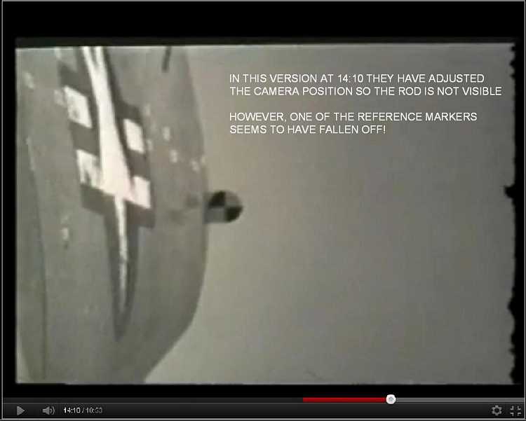
At 14:10 we see a left wing sequence where the camera direction has been changed to exclude the rod, and the mid reference marker removed perhaps deliberately?
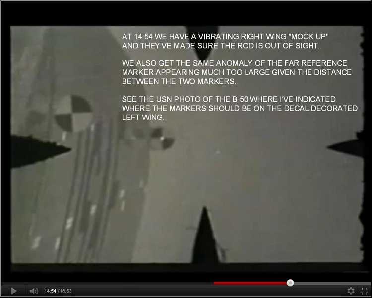
At 14:54 we have a right wing sequence.
The obvious "giveaway" in all these sequences is the orientation of the rectangular film frame to the wing. If shot from the aircraft with a conventional tripod mounted movie camera the plane of the wing would be on the long edge of the film frame, not perpendicular to it.
Regarding the "wing marker" anomaly, I'm working with a small B-50 schematic I found here:
http://www.globalsecurity.org/wmd/systems/b-50.htmIf anyone can help me out by posting a link to a better one please do so.
On a lighter note, you will notice that none of the personnel emerging from the aircraft after the mission are wearing electrically heated flying suits. Even on a hot summers day, at a height of a few thousand feet the temperature is so cold it would literally freeze the balls off a brass monkey, especially if the monkeys were filming the wings through openings in the fuselage....lol
Addendum
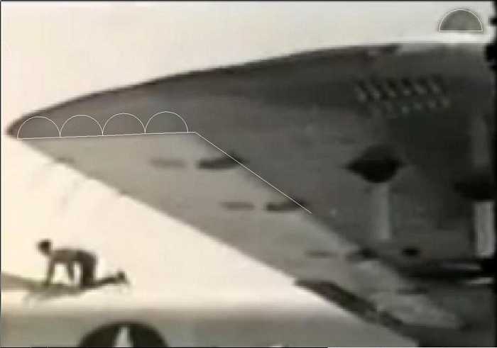
I have now put the Schematic jpg into AutoCad and blown it up to full size. The width of the B-50 flaps are 2.9 (say 3 ft). If you look at the B-50 wing tip enlarged below you can see we can fit 4 of the targets along the 3 ft flap length. This makes the diameter of the reference marker conservatively 9 inches. This means the vibrating wing frames are
DEFINITE FAKES!!! The markers are about 30 ft apart ie 40 times the diameter of the markers.
Stand two £1 coins upright on a table, the distance between them being 40 x their diameter. Now crouch down and look along the line of the coins comparing the apparent size of the near coin to that of the distant one.......now compare this with the size of the markers in the fake wing deflection clips! .....QED!
